Welding Pressure Regulator
What is a welding pressure regulator?
Welding safety requires knowledge of the equipment being used, specifically proper setup, handling, maintenance, and safety practices. One piece of equipment that is common to all gas, or oxyfuel, welding processes is the welding pressure regulator.
How Welding Pressure Regulators Work
Understanding the mechanics of a regulator is key to appreciating its role. Most designs rely on a spring-loaded diaphragm system to balance forces and maintain outlet pressure.High-pressure gas enters the regulator via the inlet (connected to the cylinder valve). It pushes against a sealed valve stem. An adjusting screw compresses a spring, which flexes a flexible diaphragm. This movement opens the high-pressure valve just enough to allow gas into the low-pressure chamber.As gas flows out to the torch, outlet pressure drops. The diaphragm senses this, flexing to open the valve further—restoring balance. Conversely, if pressure rises (e.g., no flow), the diaphragm pushes back, closing the valve. This dynamic equilibrium delivers constant pressure despite fluctuating cylinder levels.Gauges provide visibility:
- Cylinder pressure gauge: Shows remaining gas (e.g., 2,000 PSI full for argon).
- Delivery pressure gauge (or flowmeter): Indicates outlet PSI or cubic feet per hour (CFH).
For inert gases like argon, flowmeters with a floating ball in a tapered tube offer precise CFH readings, often back-pressure compensated to ignore hose restrictions. Safety features include relief valves (vent excess pressure) and burst discs (one-time rupture for catastrophic overpressure).Single-stage regulators perform this in one step—simple but prone to “decay” as cylinders empty. Two-stage models use tandem chambers for rock-steady output, ideal for precision TIG.
Types of welding regulators
Flowmeter regulator
A flowmeter regulator combines a pressure regulator and a flow meter (a device used to measure a fluid’s flow rate or quantity, such as gas, liquid, or steam). A flowmeter regulator controls gas flow from the outlet with a fixed outlet pressure and variable orifice. The device is designed to measure and control gas flow through a pipe or conduit by adjusting the size of the orifice (opening) through which the gas flows. The outlet pressure, or the pressure at which the gas exits the flowmeter regulator, is fixed and does not change. On the other hand, the orifice can be adjusted to vary the gas flow through it. This allows for the precise control of the gas flow and ensures that the outlet pressure remains constant, regardless of changes in the flow rate. This type of flowmeter regulator is commonly used in industrial applications such as gas pipelines, chemical plants, and manufacturing facilities to control the flow of gasses such as natural gas and propane.
Dual flowmeter
In welding, a dual flowmeter is typically used to measure and control the flow of two gasses: the shielding gas and the fuel gas.
The shielding gas, typically argon or a blend of argon and other gasses, is used to protect the weld pool and the surrounding area from oxidation and other forms of contamination.
The fuel gas, typically acetylene or propane, provides the heat needed to melt the metal and create the weld.
A dual flowmeter for welding typically consists of two flow sensors, one for each gas and a control unit that allows the user to adjust the flow rate of each gas separately. The flow sensors measure the flow of each gas and send the data to the control unit, which then displays the flow rate of each gas on a digital display. The user can then adjust the flow rate of each gas using the control unit, ensuring that the correct amount of each gas is used for the welding process.
Types of Welding Pressure Regulators
- Single-Stage: Reduces pressure in one go. Affordable, lightweight; common for hobby MIG/TIG. Output drops slightly as tank empties—adjust periodically. Best for short sessions.
- Two-Stage: Dual chambers mimic a “regulator feeding another.” Delivers unwavering pressure even from near-empty cylinders. Premium choice for professional TIG or long production runs.
By Measurement
- Pressure Gauge Regulators: Dual PSI gauges. Versatile for oxy-fuel; set delivery manually.
- Flowmeter Regulators: Tube-and-ball for CFH. Preferred for MIG/TIG shielding—intuitive, surge-resistant.
- Flowgauge: Hybrid with preset pressure and adjustable flow valve.
By Gas and Application
- Argon/CO2 (Inert): CGA-580 inlet; 0–60 CFH. Brass body for corrosion resistance.
- Oxygen: CGA-540; high-flow for cutting.
- Acetylene: CGA-510; low-pressure (max 15 PSI) to avoid decomposition.
- Propane/LPG: Similar to acetylene but different threads.
- Nitrogen/Helium: Purging or high-pressure testing; up to 800 PSI delivery.
- Specialty: Dual-flow for mixed gases; heated for CO2 to prevent freezing.
Selecting the Right Regulator
- Gas Compatibility: Check CGA standard (e.g., 580 for argon). Wrong threads? Explosion risk.
- Process Needs: MIG—20–30 CFH; TIG—10–20 CFH; Oxy-fuel—flame-specific PSI.
- Duty Rating: Light (hobby), medium (shop), heavy (industrial).
- Features: Polycarbonate covers for shatter resistance; brass vs. chrome-plated for durability.
- Budget vs. Longevity: $50 imports suffice for occasional use; $150+ pros last decades.
- Extras: Hose included? Dual gauges? Preset for machine solenoids?
Installation and Setup
- Inspect cylinder valve for damage. Stand aside—crack open briefly to blow debris (“sniff test”).
- Attach regulator: Hand-tighten, then 1/4-turn with wrench. Gauges away from you.
- Connect hose: 5/8″-18 RH for inert; check for cracks.
- Pressurize: Close adjusting knob (counterclockwise). Open cylinder slowly (1/4-turn first).
- Set pressure: Turn knob clockwise while purging line. For flowmeters, trigger torch to read accurately.
- Leak Test: Soapy water on connections—bubbles mean tighten or replace O-rings.
Safety Practices
- Never stand in front of gauges when opening cylinder.
- No oil/grease on oxygen fittings (firebomb risk).
- Secure cylinders upright; use caps when moving.
- Relief valves vent sideways—position accordingly.
- Annual inspections per BCGA/OSHA; replace every 5 years.
- Train on emergency shutoff.
Maintenance and Longevity
- Wipe with dry cloth—never solvents.
- Store capped, upright, 50–80°F.
- Replace gauges if foggy/dented.
- Diaphragm kits every 3–5 years.
- Filter impurities upstream.
Common Problems and Troubleshooting
- Leaks: Hiss or soap bubbles. Fix: New seals; don’t overtighten brass.
- Creep: Outlet rises when idle. Cause: Dirt in seat. Clean or rebuild.
- Freeze-Up: CO2 in cold. Solution: Heater blanket or slower flow.
- No Flow: Stuck valve. Tap gently or replace.
- Inaccurate Gauges: Drop damage. Calibrate or swap.
- Surge: Hose volume. Shorten hose or add restrictor.
Top Brands and Recommendations
- Harris: Century-old precision; Model 25GX medium-duty ($120–200). Bombproof brass.
- Victor (ESAB): Edge series flowmeters; surge guard standard.
- Miller Smith: Heavy-duty Series 30/40; dual-flow options.
- Lincoln Electric: Affordable prosumer; great warranties.
- YESWELDER/ARCCAPTAIN: Budget kings ($40–80); solid for hobbyists.
Advanced Tips and Innovations
- Dual-Flow: One reg, two torches—save setup time.
- Digital Regs: Bluetooth monitoring for shops.
- Eco Modes: Auto-bleed reduces waste 20%.
- Mixers: On-the-fly Argon/CO2 blends.
Working
*The flow gauge measures the shielding gas and fuel gas flow, and displays the flow rate on a gauge.
*The user can adjust the flow rate of each gas using the regulator, which controls the flow by adjusting the opening or closing of a valve.
*The flow gauge continuously monitors the flow of the gasses, and the regulator adjusts the flow rate as needed to maintain the desired flow rate.
*The flow gauge regulator ensures that the correct amount of each gas is used for the welding process. This helps maintain a high-quality weld and improves the overall efficiency of the welding process.
Welding Pressure Regulator Parts & Process
A welding pressure regulator relies on three parts to reduce the pressure of gas coming from the cylinder and traveling to the hose: the screw, the diaphragm, and the high-pressure valve. Following is an overview of the process:
Step 1: An adjusting screw is turned inward, pushing a spring into a flexible diaphragm.
Step 2: When the diaphragm is displaced by the spring, it opens the high-pressure value. This allows more gas to flow into the regulator from the cylinder.
Step 3: When the pressure of the gas cancels out the pressure from the spring, the diaphragm returns to its original position. This causes the high-pressure valve to close.
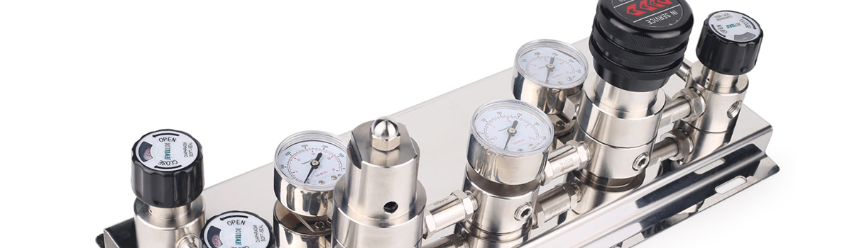
Regulator Gauges
Welding pressure regulators usually have one to two pressure gauges.
Working Pressure:
Displays the pressure of the gases in the regulator, which is always less than the pressure of the gases at the torch.
Cylinder Pressure:
Indicates the pressure and amount of gas in the cylinder.
Safety Devices
Two types of safety devices are commonly found on welding pressure regulators. They prevent extremely high pressures from damaging the regulator.
Safety Release Valves:
a valve consisting of a small ball tightly held with a spring to a seat. Once excessive pressure has been released, the valve will reset.
Safety Disc:
A thin disc the will burst to release excessive pressure. The disc must be replaced after use.
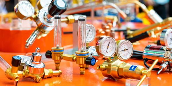
Welding gas cylinder regulator
It’s important to follow safety guidelines when oxyfuel welding. Here are some tips for using welding pressure regulators correctly.
When opening the cylinder, do not stand directly in front of the regulator. Keep regulators away from sparks or flames at the worksite.
Check for leaks in the diaphragm. If using fuel gases, set the regulator to 14 pounds per square inch gauge (psig); use 45 psig for all other gases and oxygen. Put your finger on the vent hole and apply a leak-detecting solution. If there are bubbles on the vent when you remove your finger, there is a leak.
A leaky diaphragm could be an indication of a leak in the high-pressure valve seat. This problem can cause creep: increasing pressure on the working side of the regulator. Too much pressure on the working side can damage not only the diaphragm but also the hoses, gauges, and other equipment.
When shutting down the oxyfuel system, always back off the adjusting screw to release pressure on the spring and diaphragm and prevent damage to them.
Never oil a regulator. Only clean it with a dry, oil-free towel.
Always have a trained technician perform repair work on a welding pressure regulator.