Pressure Regulator & Valves Technology
Regulators, Valves and Systems deliver a wide range of standard and custom engineered precision pressure control solutions for a diverse world market.

High Purity Gas Regulator

In the realm of advanced manufacturing and scientific research, the integrity of process gases determines the difference between success and catastrophic failure. A high purity gas pressure regulator—often abbreviated as HPGPR—serves as the cornerstone of gas delivery systems where contamination tolerance is measured in parts per trillion (ppt). These regulators reduce cylinder pressures from 2,000–4,000 psig to stable delivery pressures of 0.1–500 psig while preserving gas purity at 99.9999% (6.0 grade) or higher.
 
The global high purity gas equipment market, including pressure regulators, surpassed $12.3 billion in 2024 and is projected to grow at 7.8% CAGR through 2032, according to SEMI and IHS Markit data. Semiconductor fabrication alone consumes over 60% of this market, with each 300 mm fab requiring 1,200–1,800 specialized regulators. Beyond chips, applications span pharmaceutical bioreactors, analytical instrumentation, aerospace propulsion, and quantum computing cryogenics.
 
This article examines the engineering principles, material science, design architectures, performance specifications, application case studies, selection methodologies, installation protocols, maintenance strategies, and emerging innovations in high purity gas pressure regulators.

Core Function: Precision Pressure Control + Zero Contamination

In the world of gas delivery systems, a pressure regulator stands as a silent guardian, ensuring that the gas flowing to critical processes remains steady and pure. Its core function is twofold: delivering precision pressure control while introducing zero contamination to the gas stream. This dual role is especially vital in high-purity applications like semiconductor manufacturing, pharmaceutical production, and analytical instrumentation, where even the slightest deviation or impurity can compromise results, safety, or product quality.

Precision Pressure Control: The Primary Mission

At its heart, a regulator’s primary job is to maintain a constant outlet pressure regardless of external challenges. These challenges are relentless and come from multiple sources:
  • Changing inlet pressure: As a gas cylinder depletes, the pressure inside drops—sometimes dramatically from 3,000 psig to under 500 psig. A robust regulator compensates seamlessly, preventing downstream fluctuations.
  • Varying downstream flow demand: Processes rarely run at steady state. Flow can surge from near-zero to 100 standard liters per minute (slpm) or more in an instant. The regulator must respond without lag or overshoot.
  • Temperature fluctuations: Ambient or process heat can alter gas density and pressure. A well-designed regulator remains unfazed across wide temperature swings.
This isn’t just about stability—it’s about precision. High-purity regulators achieve outlet pressure control within ±0.01 psig across extreme operating envelopes: from near-vacuum to 1,000 psig inlet decay and flow rates up to 100 slpm. That’s equivalent to holding a column of water steady to within a fraction of a millimeter—under dynamic, real-world conditions.

How It Works: The Diaphragm-Poppet Dance

Force-Balance Principle (Simplified)
Inlet gas pressure × Poppet area = Spring force + Outlet pressure × Diaphragm area
The magic happens inside a deceptively simple mechanism:
  1. Sensing: A thin, flexible diaphragm continuously monitors outlet pressure.
  2. Response:
    • If outlet pressure drops (due to increased demand), a calibrated spring pushes the poppet open, allowing more gas to flow.
    • If outlet pressure rises (due to reduced demand or inlet surge), the gas force on the diaphragm overcomes the spring, closing the poppet.
  3. Equilibrium: This feedback loop operates in milliseconds, maintaining set-point pressure with extraordinary fidelity.
The result? A rock-steady outlet pressure that downstream instruments and processes can rely on—without electronic controllers, sensors, or power supplies. It’s pure mechanical elegance.

Zero Contamination: The High-Purity Imperative

While any regulator can control pressure, high-purity models elevate the game by ensuring the gas remains chemically unchanged. This secondary—but equally critical—function means zero added contaminants, including:
  • Particulates
  • Moisture
  • Hydrocarbons
  • Metallic ions
  • Outgassing byproducts
Even a single foreign molecule per billion can ruin a semiconductor wafer or skew an analytical result. High-purity regulators achieve this through obsessive material selection and design:
  • 316L VIM/VAR stainless steel or electropolished surfaces reduce particle shedding and adsorption sites.
  • Metal diaphragms (not elastomers) eliminate organic outgassing and permeation.
  • Tied diaphragm designs prevent gas from contacting secondary seals or lubricants.
  • Helium leak-tested assemblies (to 1×10⁻⁹ atm·cc/sec) ensure no external ingress.
The regulator doesn’t just deliver gas—it preserves its integrity from cylinder to point of use.

Why This Matters: Real-World Impact

Consider a semiconductor fab running nitrogen purge at 50 psig. A 0.05 psig drift could alter etch uniformity. A single 0.1-micron particle could kill a $10,000 wafer. Or in pharmaceutical freeze-drying, where argon blanket pressure must stay within 0.02 psig to prevent oxidation—any moisture ingress from a subpar regulator could degrade an entire batch.High-purity regulators aren’t just components—they’re trust anchors in ultra-sensitive gas chains.

Engineering Excellence in Miniature

Achieving ±0.01 psig stability over 100 slpm and 1,000 psig inlet decay isn’t trivial. It demands:
  • Ultra-low hysteresis springs
  • Precision-machined orifices
  • Large sensing areas for sensitivity
  • Damped poppet motion to prevent chatter
These features pack laboratory-grade performance into a palm-sized device that operates for years without adjustment.

High Purity vs. General-Purpose Regulators: 12 Critical Differences

Feature
General-Purpose Regulator
High Purity Regulator
Body Material
Brass, aluminum
316L SS, VIM-VAR, Hastelloy
Internal Finish
15–25 µin Ra
3–7 µin Ra electropolished
Diaphragm
Neoprene, Buna-N
316L SS, Hastelloy, Inconel
Seat
Nylon, PTFE
PCTFE, Vespel, metal-to-metal
Helium Leak Rate
1×10⁻⁶ atm-cc/sec
1×10⁻⁹ or tighter
Outgassing
ppm levels
< 10 ppt hydrocarbons
Particle Generation
0.1–1 µm
< 0.01 particles > 0.02 µm
Moisture Contribution
1–10 ppm
< 1 ppb
Purity Grade Supported
4.5 (99.995 %)
6.0–7.0 (99.9999–99.99999 %)
Cost
$50–$300
$800–$4,500
MTBF
1–3 years
5–15 years
Certifications
CGA, ISO 2503
SEMI F1, ASME BPE, ASTM F1397

Materials Science: Building a Contaminant-Free Flow Path

Base Metals

  • 16L Stainless Steel (Low Carbon): ≤ 0.03 % C prevents carbide sensitization during welding.
  • 316L VIM-VAR: Vacuum Induction Melt + Vacuum Arc Remelt reduces inclusions to < 1 ppm.
  • Hastelloy C-22: Ni-Cr-Mo alloy for Cl₂, HCl, HF.
  • Monel 400/K-500: For NH₃, marine environments.
  • Inconel 718: Cryogenic service to –196 °C.

Surface Finishing

  • Electropolishing: Removes 20–30 µm of surface metal, leaving 3–5 µin Ra and a 30–50 Å Cr₂O₃ passive layer.
  • Passivation: Citric or nitric acid forms oxide barrier; verified by < 1 ppb Fe in rinse water (ASTM A967).

 Diaphragm Technologies

Material
Permeation Rate
Temperature
Cycle Life
316L SS
Zero
–40 to 150 °C
500,000+
Hastelloy
Zero
–70 to 200 °C
400,000
Viton
10⁻⁷ cm²/s
Limited
< 50,000

Seat Materials

  • PCTFE (Kel-F): Bubble-tight shutoff, compatible with corrosives.
  • Vespel SCP-5000: < 50 ppt outgassing at 200 °C.
  • Metal-to-Metal: Lapped to < 2 helium light bands flatness.

Design Architectures

In high-purity gas delivery systems—spanning semiconductor fabrication, pharmaceutical lyophilization, analytical chemistry, and aerospace testing—the pressure regulator is the critical interface between raw cylinder pressure and the precise, contamination-free delivery required at the point of use. Unlike general-purpose regulators, high-purity models must achieve sub-0.1% pressure stability across full cylinder decay while contributing zero detectable contaminants (particles, moisture, hydrocarbons, or metallic ions) to the gas stream.

Single-Stage Architecture: Simplicity for Non-Critical Applications

Principle of Operation
The single-stage regulator performs a direct reduction from cylinder pressure (typically 2,000–3,600 psig) to the final delivery setpoint (10–150 psig) in one mechanical step. A spring-loaded diaphragm senses outlet pressure and modulates a poppet against a precision orifice. As inlet pressure decays, the spring must extend further to maintain flow, resulting in a measurable drop in outlet pressure.
Performance Characteristics
  • Supply Pressure Effect (SPE): 1–3% outlet pressure decay per 1,000 psig inlet drop.
    Example: A 100 psig setpoint may drift to 97–99 psig as the cylinder empties from 2,500 to 500 psig.
  • Flow Capacity: Up to 500 slpm (depending on Cv).
  • Response Time: <50 ms to flow transients.
  • Materials: 316L SS body, PTFE or metal seals, elastomeric diaphragm (Viton, Buna-N).
Advantages
  • Compact, lightweight, and cost-effective.
  • Minimal internal volume reduces purge time.
  • Reliable for decades in stable environments.
Limitations
  • Unacceptable drift for precision instruments.
  • Elastomeric diaphragms outgas VOCs and permeate moisture.
  • No containment if diaphragm ruptures—process gas vents to atmosphere.
Ideal Applications
  • Bulk inert gas distribution (N₂, Ar, He) in non-critical zones.
  • General laboratory use (glovebox purging, rough vacuum forelines).
  • Backup systems where redundancy mitigates drift.
Verdict: Single-stage regulators are prohibited in trace analytics (ppb-level), semiconductor front-end processes, or toxic gas service due to SPE and contamination risks.

Two-Stage Architecture: Precision Through Cascaded Control

Principle of Operation

The two-stage regulator divides pressure reduction into two independent mechanical stages:

  1. First Stage: Reduces cylinder pressure to a stable intermediate pressure (typically 400–600 psig), regardless of inlet decay.
  2. Second Stage: Fine-tunes from intermediate to final delivery (0.1–150 psig).

Each stage has its own spring, diaphragm, and poppet. The first stage absorbs inlet fluctuations; the second stage sees a near-constant supply.

Performance Characteristics
  • Total Supply Pressure Effect:< 0.1% decay over full 1,000–3,000 psig inlet range.
    Example: 50.000 ± 0.005 psig from 3,000 → 300 psig inlet.
  • Stability: ±0.01 psig across 0–100 slpm flow surges.
  • Droop: <0.5 psig at max flow.
  • Materials: 316L VIM/VAR SS, metal diaphragms (Hastelloy C-22, Inconel), PCTFE seats.
Advantages
  • Laboratory-grade stability without electronic feedback.
  • Isolates downstream processes from cylinder dynamics.
  • Enables ultra-low delivery pressures (≤0.1 psig) with precision.
Limitations
  • Larger footprint and higher cost.
  • Increased internal volume requires longer purge cycles.
  • Two potential failure points (though redundant).
Mandatory Applications
  • GC-MS, LC-MS: Carrier gas (He, H₂) must not drift >0.02 psig to maintain retention time accuracy.
  • EUV Lithography: N₂ purge at 1.5 psig ± 0.01 psig prevents optical contamination.
  • Atomic Layer Deposition (ALD): Precursor pulse timing depends on <0.05% pressure ripple.
  • Calibration gas standards: NIST-traceable blends require ±0.1% delivery.
Verdict:Two-stage is the gold standard for any process where pressure stability directly impacts yield, data integrity, or safety.

Tied-Diaphragm (Fail-Safe)Architecture: Containment for Toxic & Reactive Gases

Principle of OperationIn corrosive, toxic, or pyrophoric gas service (AsH₃, PH₃, NF₃, SiH₄, B₂H₆), a diaphragm rupture must never allow process gas to escape or atmosphere to ingress. The tied-diaphragm design achieves this via a central tie rod that mechanically links the upper and lower diaphragm plates.
Failure Sequence (Rupture Event):
  1. Diaphragm tears due to fatigue, overpressure, or chemical attack.
  2. Tie rod pulls the poppet closed, sealing the inlet.
  3. Process gas is contained within the regulator body.
  4. Atmosphere cannot enter wetted path (no contamination).
  5. Optional vent port routes trapped gas to scrubber.
Performance Characteristics
  • Leak Integrity: <1×10⁻⁹ atm·cc/sec He across diaphragm.
  • Pressure Rating: Full cylinder pressure on inlet side.
  • Materials: Hastelloy C-22 body/diaphragm, Monel tie rod, Kel-F seat.
  • SPE: Same as parent architecture (single or two-stage).

Advantages

  • SEMI S2 compliant for highly toxic gases.
  • Prevents catastrophic release in cleanrooms.
  • Enables in-situ diaphragm replacement without breaking containment.
Limitations
  • Slightly reduced sensitivity (tie rod adds mass).
  • Higher cost and complexity.
  • Requires periodic leak checks.
Mandatory Applications
  • Semiconductor dopant gases: Arsine (AsH₃), Phosphine (PH₃).
  • CVD precursors: Germane (GeH₄), Diborane (B₂H₆).
  • LED manufacturing: Ammonia (NH₃), Hydrogen Selenide (H₂Se).
  • Nuclear fuel processing: UF₆ service.
Verdict: Tied-diaphragm is non-negotiable for any gas classified as Health Hazard 1 or 2 under SEMI S2/S14.

Captured Vent & Cross-Purge Architecture: Moisture and Contaminant Exclusion

Principle of Operation
Even with metal diaphragms, trace moisture or outgassed species can accumulate in regulator dead legs. The captured vent and cross-purge system eliminates this:
  1. Captured Vent: Relief valve discharge is routed to a dedicated port connected to a scrubber or flare—never to atmosphere in the cleanroom.
  2. Cross-Purge: A continuous 0.1–1 slpm N₂ sweep flows from a purge inlet, across the diaphragm backside, and out the vent port.
Performance Characteristics
  • Moisture Removal: <1 ppb H₂O in outlet gas within 30 minutes of purge initiation.
  • Outgassing Control: Sweeps away polymer degradation byproducts.
  • Particulate Control: Purge flow prevents stagnant zones.
  • Vent Capacity: Handles full relief flow (up to 50 slpm).
Advantages
  • Enables sub-ppb purity in reactive gas service (HCl, WF₆, Cl₂).
  • Allows real-time moisture monitoring via analyzer on vent line.
  • Compatible with automated purge sequencing.
Limitations
  • Requires external N₂ source and flow control.
  • Adds plumbing complexity.
  • Increases N₂ consumption.
Mandatory Applications
  • Epitaxial growth (Si, GaN): Moisture causes stacking faults.
  • Laser gas delivery (excimer, CO₂): H₂O absorbs UV wavelengths.
  • Metrology tools: FTIR, RGA require <1 ppb H₂O, O₂.
  • Pharmaceutical GMP lines: Prevents hydrate formation.
Future Trends in High-Purity Regulator Design
  1. Integrated Pressure Transducers: Hybrid electro-mechanical control for <0.001 psig stability.
  2. Additive-Manufactured Flow Paths: Eliminate welds, reduce dead volume.
  3. Smart Diagnostics: Embedded sensors detect diaphragm fatigue, moisture ingress.
  4. Zero-Dead-Volume Designs: For ppq-level contaminant control in quantum computing gas systems.

Purity Grades and Contamination Sources

The “N” Purity Scale

Grade
Purity
Typical Impurities
5.0
99.999 %
< 10 ppm total
6.0
99.9999 %
< 1 ppm total
UHP
99.99999 %
< 1 ppb O₂, H₂O, THC

Four Contamination Pathways

  1. Outgassing: Organics from elastomers, lubricants.
  2. Permeation: H₂O, O₂ through seals.
  3. Particle Shedding: Wear, welding slag.
  4. Moisture Ingress: Leaks, improper purging.

Quantified Risk Example

A 10 µin Ra surface adsorbs 0.8 monolayers of H₂O at 50 % RH. Electropolishing to 5 µin Ra reduces this to 0.12 monolayers.

Real-World Applications

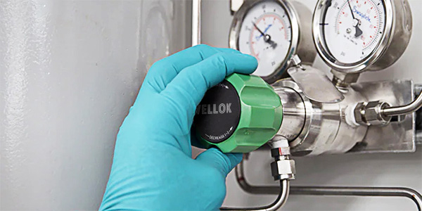
Semiconductor EUV Lithography

  • Gas: N₂ purge, 300 slpm @ 80 psig
  • Regulator: Two-stage 316L VIM-VAR, 3 µin Ra, tied-diaphragm
  • Purity: < 100 ppt H₂O, O₂
  • Result: Reduced particle defects by 68 %

GC-MS Helium Carrier

  • Flow: 25 ml/min ± 0.05 %
  • Regulator: Single-stage, 0.006 Cv, 10⁻⁹ leak rate
  • Outcome: Detection limit improved from 50 ppt to 8 ppt

Biopharma CO₂ pH Control

  • Pressure: 12 psig ± 0.02 psig
  • Regulator: Sanitary tri-clamp, ASME BPE, 5 µin Ra
  • Validation: 21 CFR Part 11 data logging
  • Result: Batch pH variation < 0.01 units

Aerospace Hydrazine Propulsion

  • Fluid: N₂H₄ vapor
  • Regulator: Monel, triple CVD coating
  • MTBF:> 75,000 hours

Selection and Sizing in 7 Steps

Step 1: Define Gas

  • Chemical formula
  • Corrosivity (pH, reactivity)
  • Required purity (ppb O₂, H₂O, THC)

Step 2: Pressure & Flow

  • Max inlet: 3,000 psig
  • Delivery: 50 psig
  • Max flow: 150 slpm N₂

Step 3: Calculate Cv

For subcritical flow (P₂ > 0.5 P₁):
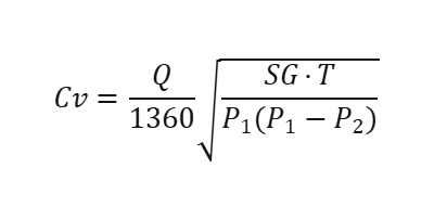
Example:
Q = 150 slpm, SG = 0.97 (N₂), T = 520 °R, P₁ = 500 psig, P₂ = 50 psig
Cv = 0.08
Step 4: Droop & Decay

  • Target droop: < 0.2 psig / 100 slpm
  • Supply pressure effect: < 0.02 % / 100 psig

Step 5: Environment

  • Temperature: –20 to 60 °C
  • Hazardous area: Class I Div 2
  • Vibration: 5 g @ 10–500 Hz

Step 6: Compliance

  • SEMI F1 (materials)
  • ASME BPE (sanitary)
  • EN 10204 3.1 MTRs

Step 7: Lifecycle Cost

Factor
Cost Impact
Initial price
$1,800
MTBF 10 yrs
–$1,200 maintenance
Yield gain
+$15,000 / tool / year

Installation, Startup, Maintenance

Pre-Installation

  1. Helium leak test at factory (< 10⁻⁹ atm-cc/sec)
  2. N₂ purge cylinder 15 volumes
  3. Cleanroom assembly (ISO Class 5)

Mounting

  • Vertical, outlet down
  • Independent bracket (no pipe stress)
  • 1/4″ EP tubing, orbital welded

Startup Sequence

  1. Close all valves
  2. Open cylinder 1/4 turn per second
  3. Set regulator 10 % high
  4. Open downstream slowly
  5. Adjust to exact setpoint
  6. In-situ He leak check

Maintenance Schedule

Interval
Task
3 months
External leak check
12 months
Diaphragm visual
5 years
Full rebuild
After upset
Immediate RGA test

Standards and Certifications

Standard
Requirement
SEMI F1
Material compatibility
SEMI S2
Toxic gas safety
CGA E-4
Performance testing
ASME BPE
Biopharma surfaces
ASTM F1397
Electropolish spec
ISO 7291
Gas compatibility

Future Innovations (2025–2030)

  1. Smart Regulators
    • MEMS pressure sensor
    • Bluetooth diagnostics
    • AI predicts diaphragm failure 30 days early
  2. Additive Manufacturing
    • 3D-printed Hastelloy flow paths
    • < 0.3 cc internal volume
  3. Advanced Coatings
    • ALD Al₂O₃: 100 % moisture barrier
    • DLC seats: 75 HRC, zero wear
  4. Green Gas Compatibility
    • F₂/He for NF₃ replacement
    • H₂ at 7.0 purity (< 1 ppt S)
  5. Modular Design
    • Field-replaceable cartridge in < 5 minutes

Conclusion

The Unsung Guardian of Process IntegrityA high purity gas pressure regulator is far more than a pressure reducer. It is a micro-contamination firewall, a precision stability engine, and a safety sentinel rolled into a palm-sized package.From the electropolished 316L VIM-VAR body to the tied Hastelloy diaphragm, every feature exists to answer one question:
“Will this molecule reach the process unchanged?”
In semiconductor fabs, analytical labs, biopharma suites, and spacecraft—where purity is non-negotiable—the high purity regulator stands as the final, invisible line of defense.Understanding its materials, designs, and protocols empowers engineers to select, install, and maintain these devices with confidence. The result? Higher yields, safer operations, and processes that push the boundaries of science and manufacturing.