
Regulator Manufacturer Tel: +86 13380377051
Regulator Manufacturer Tel: +86 13380377051
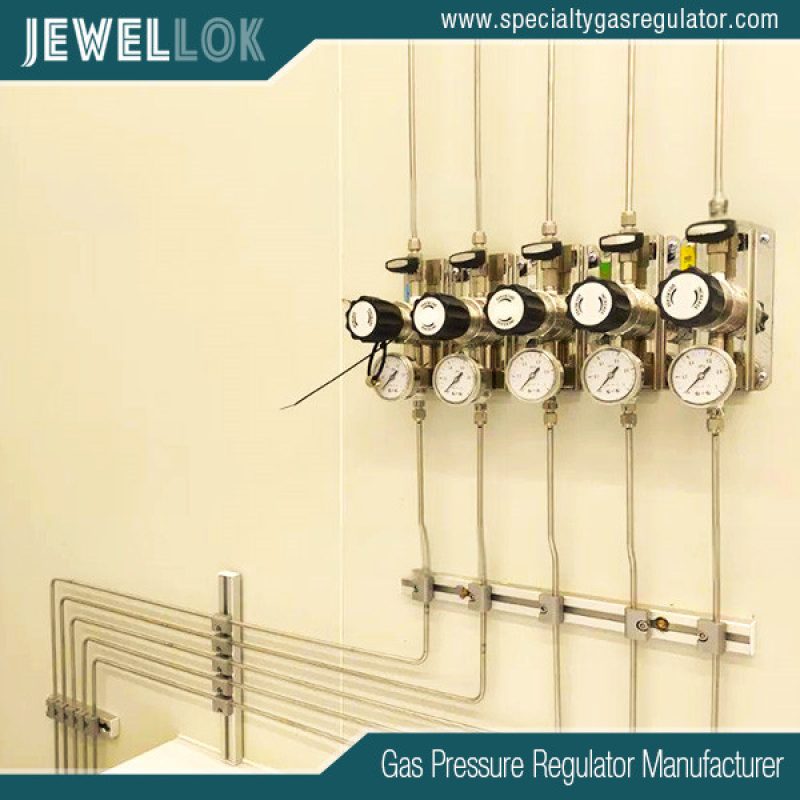
How Do You Install, Pressure-Test, and Leak-Test a Laboratory Gas Distribution System?
Introduction
Laboratory gas distribution systems (GDS) deliver high-purity, reactive, toxic, flammable, and inert gases from primary supply sources—such as gas cylinder banks, cryogenic dewars, or bulk storage tanks—directly to analytical equipment (e.g., GC-MS, ICP-MS, LC-MS) and chemical reactors. In high-purity and ultra-high-purity (UHP) environments, an improperly designed or installed piping network can cause analytical signal baseline noise, sample contamination, catalyst degradation, or severe safety hazards including fire, explosion, chemical asphyxiation, and toxic exposure.
Ensuring system integrity requires strict adherence to industry standards, including ASME B31.3 (Process Piping), NFPA 55 (Compressed Gases and Cryogenic Fluids Code), CGA G-4.1 (Cleaning Equipment for Oxygen Service), and SEMI S2/SEMI F19. This technical article details the sequential engineering procedures for installing, pressure-testing, and leak-testing high-purity laboratory gas distribution networks.

Part 1: Installation Practices for High-Purity Laboratory Gas Systems
1. Material Selection & Compatibility
Choosing appropriate piping, tubing, and component metallurgy is critical for preventing gas degradation, corrosion, and catastrophic failure.
-
316L Stainless Steel (Seamless / Electro-Polished): The standard material for UHP gases (e.g., Argon, Helium, Hydrogen, Nitrogen). Stainless steel tubing with an Electro-Polished (EP) inner surface finish ($Ra \le 0.25\ \mu\text{m}$ / $10\ \mu\text{in}$) minimizes surface adsorption and particle generation.
-
Copper Tubing (ACR / Degreased): Suitable only for low-purity, non-corrosive, non-flammable utility gases such as compressed air or low-grade nitrogen. Copper must never be used with acetylene due to the risk of forming explosive copper acetylides.
-
Exotic Alloys (Hastelloy C-22, Monel, Inconel): Required for highly corrosive gases such as dry/wet hydrogen chloride ($\text{HCl}$), chlorine ($\text{Cl}_2$), and fluorine compounds.
-
Polymers (PTFE, PFA, PVDF): Used for low-pressure corrosive gas applications or flexible pigtail connections, though permeability must be evaluated for trace-level analytical applications.
2. Tube Preparation and Cutting
Poor tube end preparation introduces burrs, swarf, and metal particulate contamination, compromising orbital welds and compression fitting seals.
-
Cutting: Use a high-precision rotary tube cutter or orbital pipe saw equipped with a dedicated stainless steel blade. Do not use standard hacksaws or abrasive cutoff wheels.
-
Deburring & Facing: Apply an automatic electric tube-facing tool to ensure the tube end is perfectly square ($\le 0.5^\circ$ cut angle deviation) with zero internal or external burrs.
-
Cleaning: Wipe the tube interior and exterior with lint-free cleanroom wipes soaked in electronics-grade isopropyl alcohol (IPA, $>99.9\%$ purity) to eliminate grease, oils, and particulate matter.
3. Joining Techniques: Swagelok-Style Compression vs. Orbital Welding
A. Compression Fittings (Twin-Ferrule Designs)
-
Twin-ferrule mechanical compression fittings (e.g., Swagelok, Gyrolok, Parker A-LOK) are ideal for modular connection points, valve manifolds, and point-of-use (POU) regulators.
-
Installation Step: Insert the tubing completely into the fitting body until it seats firmly against the shoulder. Hand-tighten the nut, then apply the manufacturer-specified turns (typically $1\frac{1}{4}$ turns from finger-tight for sizes above $1/8\text{“}$ to $1\text{“}$) using a backup wrench on the fitting body.
-
Inspection: Verify proper swaging using a gap inspection gauge before pressurization.
       Twin-Ferrule Compression Assembly Concept:
       [Nut] ---> [Back Ferrule] ---> [Front Ferrule] ---> [Fitting Body Shoulder]
B. Automatic Orbital TIG Welding
-
For permanent, ultra-clean runs, non-consumable Automatic Orbital Gas Tungsten Arc Welding (GTAW) is preferred.
-
Purging Protocol: Purge the interior of the tubing with continuous high-purity Argon gas (Grade 5.0, $>99.999\%$) at a controlled flow rate and pressure to prevent interior oxidation (“sugaring”).
-
Welding Parameters: Weld parameters must be pre-programmed according to wall thickness and diameter. Perform coupon testing before production welds.
4. Layout, Support, and Contamination Prevention
-
Slope and Drain Points: Incline horizontal gas runs slightly toward drop legs or purge valves if liquid condensation is possible.
-
Support Spacing: Secure tubing with unistrut channels and rubber-cushioned clamps at designated intervals (e.g., every $1.5\text{ m}$ to $2.0\text{ m}$ for $1/4\text{“}$ to $1/2\text{“}$ tubing) to absorb vibration and prevent stress fatigue.
-
Capping: Keep open tube ends capped at all times using cleanroom vinyl caps until the moment of final joining.
Part 2: Pneumatic Pressure Testing (Proof and Strength Testing)
Pressure testing confirms the structural strength of the assembly and validates that components can sustain operational pressures without bursting or yielding permanently.
Safety Warning: Hydrostatic testing with water introduces moisture contamination that is nearly impossible to eliminate from high-purity gas lines. Therefore, Pneumatic Testing using dry, oil-free UHP Nitrogen or Argon gas must be utilized.
+-----------------------------------------------------------------------------------+
|                            PNEUMATIC TEST SCHEMATIC                               |
|                                                                                   |
|  [ Nitrogen ] ---> [ Pressure ] ---> [ Isolation ] ---> [ Calibrated ] ---> [ System |
|  [ Source   ]      [ Regulator]      [  Valve    ]      [  Gauge    ]      [ Under Test]
|                                                               ^                   |
|                                                               |                   |
|                                                      [ Relief Valve ]             |
+-----------------------------------------------------------------------------------+
1. Test Pressure Calculation
According to ASME B31.3 (Section 345.5), the pneumatic test pressure ($P_T$) must be calculated as:
Where $P_D$ is the Maximum Allowable Design Pressure of the system.
Example: For a high-pressure manifold section rated at $200\text{ bar}$ ($2,900\text{ psi}$), the pneumatic test pressure is set to $220\text{ bar}$ ($3,190\text{ psi}$).
2. Step-by-Step Pneumatic Pressure Testing Protocol
-
Isolation & Safety Setup:
-
Isolate delicate analytical instruments, mass flow controllers (MFCs), rupture discs, and low-pressure sensors using line valves or blanking plugs.
-
Erect safety barriers around the test loop and depressurize non-essential adjacent areas.
-
-
Instrument Preparation:
-
Install a calibrated, certified digital pressure gauge with a scale maximum equal to $1.5\times$ to $2\times$ the test pressure.
-
Install an overpressure safety relief valve set to open at $110\%$ of the pneumatic test pressure.
-
-
Incremental Pressurization Steps:
-
Step 1: Pressurize the system gradually to $0.5\text{ bar}$ ($7\text{ psi}$) or $10\%$ of $P_T$, whichever is lower. Perform an initial preliminary check for major open ports or gross errors.
-
Step 2: Increase system pressure in stages of $25\%$ of $P_T$, pausing at each level for at least 10 minutes to check pressure stability.
-
Step 3: Reach full test pressure ($110\%$ of $P_D$). Hold for a minimum hold-time of 30 minutes (or longer for large-volume systems).
-
-
Pass/Fail Criteria:
-
System holds pressure without dropping, after compensating for ambient temperature fluctuations using the ideal gas law:
$$\frac{P_1}{T_1} = \frac{P_2}{T_2}$$ -
No structural deformation or component yielding observed.
-
Part 3: Leak Testing Methodologies
Once structural integrity is established via pneumatic strength testing, the system must undergo targeted leak testing to discover microscopic leak paths.
+-----------------------------------------------------------------------------------------+
|                               LEAK DETECTION METHODS COMPARISON                         |
+------------------------------+---------------------------+------------------------------+
| Method                       | Detection Limit           | Primary Application          |
+------------------------------+---------------------------+------------------------------+
| Bubble Solution Test         | 10^-2 to 10^-3 mbar·L/s   | General Utility Lines        |
| Pressure Decay Test          | 10^-3 to 10^-4 mbar·L/s   | Entire Network Hold Tests    |
| Helium Mass Spectrometry     | 10^-8 to 10^-11 mbar·L/s  | UHP & Toxic/Flammable Systems|
+------------------------------+---------------------------+------------------------------+
Method A: Bubble Leak Testing (Snoop / Soap Solution)
Suitable for low-purity lines, preliminary checks, or non-critical gas networks.
-
Procedure: Apply a non-corrosive, high-viscosity bubble solution (e.g., Swagelok Snoop) around every mechanical joint, weld interface, valve stem, and threaded connection while the system is pressurized to operational pressure.
-
Observation: Continuous bubble formation indicates a leak.
-
Limitations: Low sensitivity ($\sim 10^{-2}$ to $10^{-3}\ \text{mbar}\cdot\text{L/s}$). Liquids must be completely washed off with deionized water after testing to prevent halide-induced stress corrosion cracking on stainless steel.
Method B: Pressure Decay (Pressure Hold) Testing
A macro-level system test capable of verifying overall gas tightness across extended periods.
-
Procedure:
-
Pressurize the dry network to $100\%$ of maximum working pressure with pure Nitrogen or Argon.
-
Isolate the supply source and record initial pressure ($P_1$) and temperature ($T_1$).
-
Allow the system to sit idle for 12 to 24 hours.
-
Record final pressure ($P_2$) and temperature ($T_2$).
-
-
Calculation:
$$\Delta P_{\text{corrected}} = P_1 – \left( P_2 \times \frac{T_1}{T_2} \right)$$ -
Pass Criteria: $\Delta P_{\text{corrected}} = 0$ over the test duration, accounting for gauge precision tolerances.
Method C: Helium Mass Spectrometer Leak Testing (UHP Standard)
The gold standard for ultra-high-purity, flammable, pyrophoric, or toxic gas distribution systems (e.g., silane, arsine, hydrogen). Capable of detecting leak rates down to $10^{-9}$ to $10^{-11}\ \text{mbar}\cdot\text{L/s}$.
1. Out-Side In Method (Vacuum / Hood Technique)
Used to test individual components or assembled sub-systems capable of holding an internal vacuum.
       [Helium Mass Spec Detector] <--- [Vacuum Pump] <--- [System Under Vacuum]
                                                                  ^
                                                                  |
                                                       (Helium Gas Sprayed Outside)
-
Procedure:
-
Connect a Helium Mass Spectrometer Leak Detector (MSLD) to the internal volume of the gas piping network.
-
Evacuate the piping system down to a high vacuum level ($<10^{-3}\ \text{mbar}$).
-
Spray a fine jet of pure Helium gas around external joints, welds, fittings, and valve packing glands.
-
If a micro-leak exists, Helium is drawn inside the pipe and instantly detected by the mass spectrometer’s analyzer cell.
-
2. Inside-Out Method (Sniffer Technique)
Used when the piping network cannot be evacuated or when working with high-pressure gas lines.
-
Procedure:
-
Charge the gas line with a mixture of $10\text{–}100\%$ Helium balanced with dry Nitrogen to working operational pressure.
-
Move a sniffer probe attached to the MSLD along the external surface of welds, fittings, and flanges at a maximum speed of $15\text{ mm/sec}$.
-
Maintain a probe distance of $\le 3\text{ mm}$ from the potential leak site.
-
An audible signal and quantitative readout indicate localized leaks.
-
Part 4: System Purging, Passivation, and Commissioning
Once pressure and leak testing are completed successfully, the gas line must be converted from test condition to operational UHP state.
+-----------------------------------------------------------------------------------+
|                        COMMISSIONING WORKFLOW PIPELINE                            |
|                                                                                   |
|   [ Pass Leak Test ] --> [ Vacuum Evacuation ] --> [ Dynamic N2 Purging ]        |
|                                                             |                     |
|                                                             v                     |
|   [ Ready for Gas  ] <-- [ Moisture & O2 Check ] <-- [ Outgassing / Bakeout ]     |
|       Service            (Purity Validation)            (If Required)             |
+-----------------------------------------------------------------------------------+
-
Evacuation and Cyclic Purging:
-
Perform repeated cycle purges (pulling vacuum down to $<100\ \mu\text{m}\text{Hg}$ followed by pressurizing with UHP Nitrogen to $3\text{ bar}$) a minimum of 10 to 20 times. This strips adsorbed atmospheric moisture ($\text{H}_2\text{O}$) and Oxygen ($\text{O}_2$) from internal walls.
-
-
Moisture and Oxygen Analytical Validation:
-
Connect trace moisture and oxygen analyzers at the point of use (POU).
-
Continue purging until moisture levels drop below $<10\ \text{ppb}$ (or the process target) and oxygen levels match baseline supply purity.
-
-
Labelling and Documentation:
-
Affix permanent labels according to ANSI A13.1 indicating gas name, chemical formula, direction of flow, and working pressure.
-
Archive welding logs, coupon records, calibration certificates, and leak test reports into the laboratory’s facility management file.
-
Summary Checklist for Site Engineers
| Phase | Core Step | Acceptance Standard / Target |
| 1. Installation | Tube Cutting & Facing | Square cut ($\le 0.5^\circ$), zero burrs, cleaned with $>99.9\%$ IPA |
| Ferrule Tightening | $1\frac{1}{4}$ turns past finger-tight; verified with gap gauge | |
| Purge Welding | Inner purge Argon Grade 5.0; zero interior oxidation | |
| 2. Pressure Test | Pneumatic Hold | $1.1 \times P_D$ for $\ge 30\text{ min}$; zero temperature-adjusted loss |
| 3. Leak Test | Helium Vacuum / Sniffer | Leak rate $< 1 \times 10^{-9}\ \text{mbar}\cdot\text{L/s}$ for UHP service |
| 4. Commissioning | Cycle Purging | Moisture $< 10\ \text{ppb}$, Oxygen match source baseline |
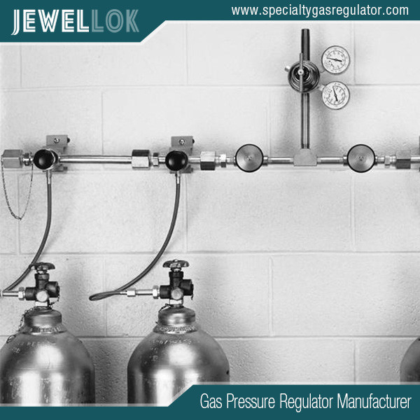
Conclusion
Installing and certifying a laboratory gas distribution network requires precise engineering controls at every phase. By combining clean room material preparation, rigorous compression or orbital welding standards, standardized pneumatic testing per ASME B31.3, and high-sensitivity helium mass spectrometry leak detection, lab facility managers can ensure long-term operational performance, gas purity, and personal safety.
For more about how do you install, pressure-test, and leak-test a laboratory gas distribution system, you can pay a visit to Jewellok at https://www.specialtygasregulator.com/product-category/specialty-gas-cabinet/ for more info.
-
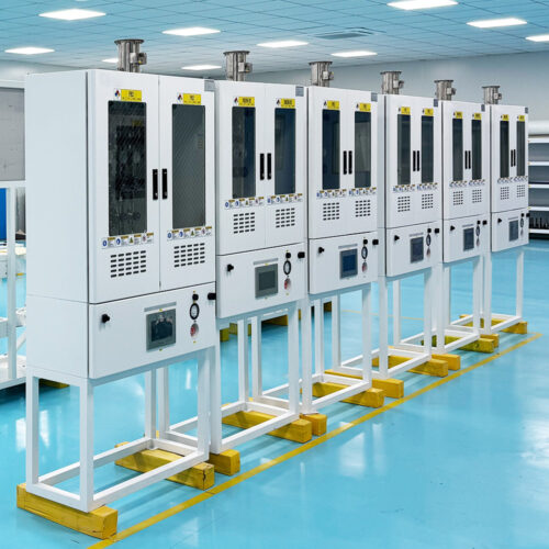
Integrated Gas Cabinets and Exhaust Gas Scrubber System for Ammonia and Hydrogen Chloride Industrial Emission Control
-
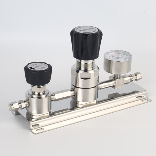
High Purity High Flow Pressure Control Regulators & Valves Gas Stick Assemblies JSR-2TG Series
-
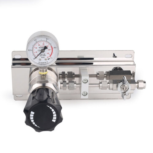
High Purity Gas Cylinder Semi Automatic Changeover Manifold Regulator Panel 3000psig Stainless Steel Gas Control Panel 1/8 Npt With Gauge
-
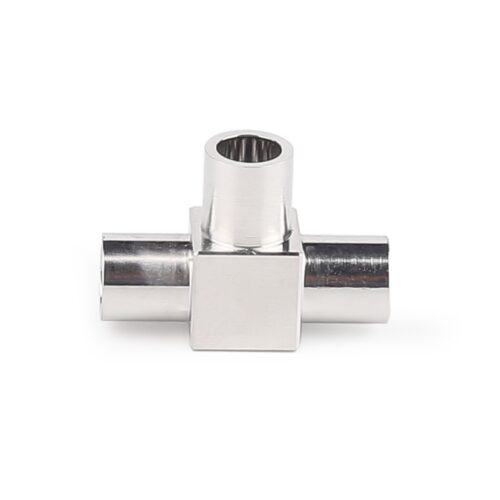
Stainless Steel Ultra High Purity Mini Butt Weld Mini Tee Reducer MTRW Series Fittings
-
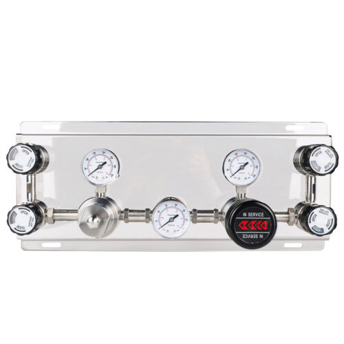
Semi Automatic And Automatic Switching Speicialty Gas Changeover Manifold Panel With Semiconductor Valve Manifold Box Gas Pressure Regulators
-
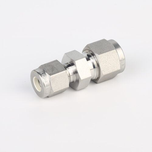
763L Stainless Steel High Purity Pressure Reducing Union Fittings And Tubing Pressure Reducing Valve Adjustment
-
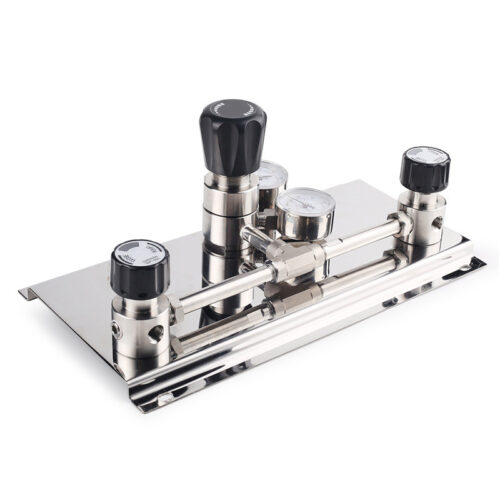
High Purity Semi-Auto Stainless Steel Changeover Manifold System, Nitrogen High Pressure Control Panel With Semiconductor Valve Manifold Box Diaphragm Valves
-
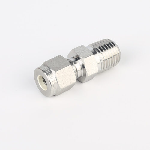
768L Stainless Steel Male Tube Butt Weld Connector | Clean Weld Fittings And Ultra-High Purity Fittings