
Regulator Manufacturer Tel: +86 13380377051
Regulator Manufacturer Tel: +86 13380377051
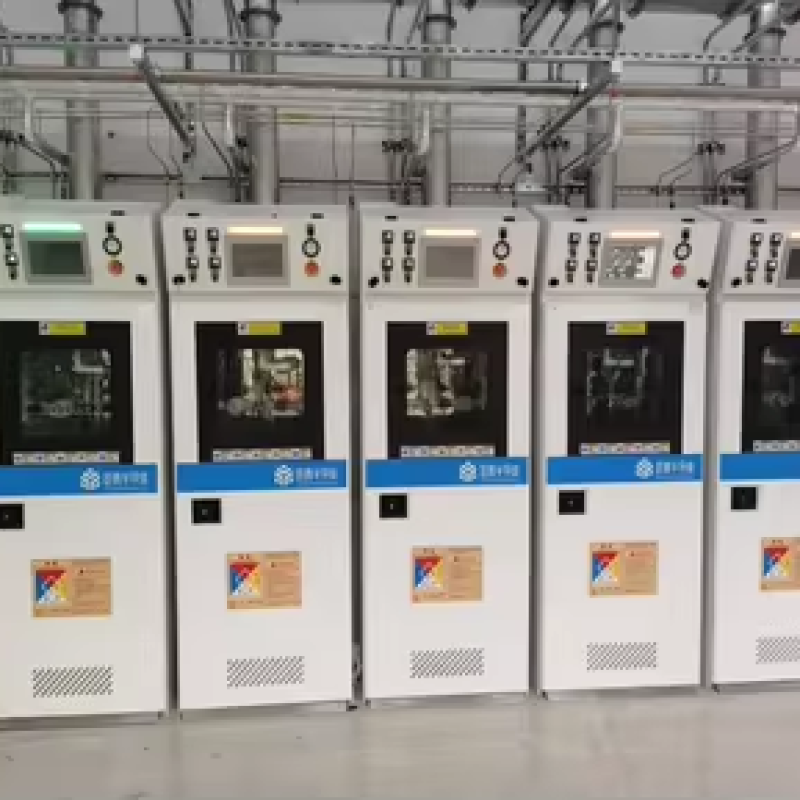
Centralized Laboratory Gas Supply System: Design, Components and Installation Guide
A centralized laboratory gas supply system provides a safe, reliable, and efficient method for distributing gases from a central source to multiple laboratory workstations, analytical instruments, fume hoods, and process equipment. Instead of connecting individual gas cylinders directly to each point of use, a centralized system uses a controlled gas distribution network consisting of gas sources, manifolds, regulators, pipelines, valves, pressure control devices, monitoring systems, and terminal outlets.
Centralized laboratory gas systems are widely used in chemical laboratories, pharmaceutical facilities, universities, hospitals, research institutions, semiconductor laboratories, and industrial testing centers. Proper system design is essential because laboratory gases may include inert, oxidizing, flammable, toxic, corrosive, or high-purity gases.
This guide explains the key considerations for centralized laboratory gas supply system design, major components, installation procedures, pressure control, material selection, safety requirements, and maintenance.
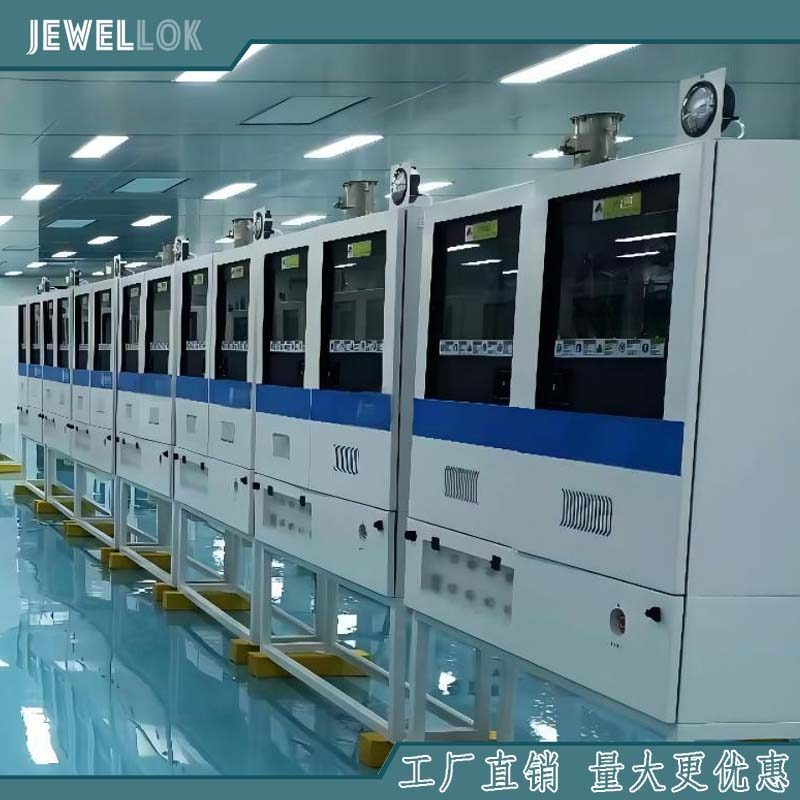
1. What Is a Centralized Laboratory Gas Supply System?
A centralized laboratory gas supply system transports gas from a centralized source to multiple points of use through a dedicated piping network.
Typical gas sources include:
- Nitrogen (N₂)
- Oxygen (O₂)
- Argon (Ar)
- Helium (He)
- Carbon dioxide (CO₂)
- Hydrogen (H₂)
- Compressed air
- Vacuum
- Specialty and calibration gases
- Toxic or corrosive process gases
A typical system consists of a gas cylinder or bulk gas source, source manifold, primary pressure regulator, distribution pipeline, zone isolation valves, secondary regulators, pressure gauges, gas monitoring equipment, and point-of-use outlets.
The basic gas flow can be represented as:
Gas Source → Manifold → Primary Regulator → Distribution Pipeline → Zone Valve → Secondary Regulator → Point-of-Use Outlet → Laboratory Equipment
The exact configuration depends on the gas type, required purity, operating pressure, flow rate, number of outlets, and laboratory layout.
2. Why Use a Centralized Gas Supply System?
Centralized gas distribution offers several advantages over individual cylinder connections.
Improved Safety
Moving gas cylinders away from laboratory workstations can reduce cylinder handling and minimize the number of high-pressure containers inside occupied laboratory areas. Centralized source areas can also be designed with appropriate ventilation, gas detection, access control, and emergency shutoff systems.
Stable Gas Pressure
A properly engineered pressure control system can provide relatively stable pressure to multiple instruments. This is particularly important for analytical instruments and laboratory processes requiring consistent gas flow.
Easier Cylinder Management
Instead of manually changing cylinders at multiple laboratory benches, operators can manage cylinders or bundles from a designated gas storage or gas supply area.
Better Laboratory Organization
Fixed piping eliminates numerous flexible hoses and individual cylinder connections around laboratory workspaces, helping create a cleaner and more organized environment.
Scalability
A centralized system can be designed with additional outlets or distribution zones, making it easier to expand the laboratory as equipment requirements increase.
3. Centralized Laboratory Gas System Design Considerations
The design should begin with a detailed assessment of gas demand and laboratory requirements.
Gas Type and Application
Different applications require different gas specifications. For example, nitrogen used for general laboratory purging may have different purity requirements from nitrogen supplied to analytical instruments or semiconductor research equipment.
The designer should determine:
- Gas type
- Required purity
- Required pressure
- Maximum and normal flow rate
- Operating temperature
- Number of points of use
- Simultaneous demand
- Required redundancy
- Gas compatibility with piping materials
The system should be designed according to the actual process requirements rather than simply selecting a standard pipeline size.
Pressure Requirements
Gas cylinders and bulk sources can operate at significantly higher pressure than laboratory equipment. Therefore, pressure reduction normally occurs in stages.
A typical arrangement may include:
High-Pressure Source → Primary Regulation → Distribution Pressure → Point-of-Use Regulation
Two-stage pressure reduction can improve pressure stability and provide better control for sensitive applications.
The design should consider both normal operating pressure and maximum possible pressure. Pressure relief devices should be incorporated where necessary to protect downstream components from overpressure.
Flow Rate and Diversity
The pipeline must accommodate the required gas flow without excessive pressure drop.
A system serving ten laboratory instruments does not necessarily require ten instruments to operate simultaneously at maximum flow. The designer should establish a realistic diversity factor based on actual laboratory operations.
Incorrect flow calculations may result in:
- Excessive pressure drop
- Insufficient gas supply
- Unstable instrument operation
- Undersized regulators
- Excessive pipeline velocity
Therefore, pipe sizing should consider source pressure, downstream pressure, gas properties, pipe length, fittings, flow rate, and simultaneous demand.
4. Major Components of a Centralized Laboratory Gas System
4.1 Gas Source
The gas source may consist of individual cylinders, cylinder bundles, liquid storage tanks, microbulk systems, or bulk gas supply equipment.
For applications requiring continuous operation, an automatic changeover system can be used to switch between primary and reserve gas banks.
4.2 Gas Manifold
The gas manifold connects multiple cylinders to a common supply line. It may include isolation valves, check valves, pressure regulators, flexible connections, pressure gauges, and safety relief devices.
For critical applications, automatic changeover manifolds can reduce supply interruptions by switching to a reserve bank when the primary bank reaches a preset pressure.
4.3 Pressure Regulators
Pressure regulators reduce source pressure to a suitable distribution pressure.
A centralized system may use:
- Primary regulators
- Line regulators
- Secondary regulators
- Point-of-use regulators
For high-purity laboratory applications, regulators should be selected for low internal volume, appropriate materials, reliable sealing, and compatibility with the gas.
4.4 Distribution Piping
The pipeline transports gas from the source to laboratory points of use.
Common materials include stainless steel, copper, and specialized polymer tubing depending on gas type and purity requirements.
For high-purity gases, 316L stainless steel is frequently selected because of its corrosion resistance, mechanical strength, and suitability for high-purity gas distribution when properly processed and installed.
Pipeline construction may use orbital welding, compression fittings, face-seal fittings, or other connection technologies depending on the system specification.
4.5 Isolation Valves
Isolation valves allow individual laboratory zones or equipment branches to be shut off without interrupting the entire gas supply.
Typical locations include:
- Gas source
- Main distribution header
- Laboratory zones
- Branch lines
- Equipment connections
Clearly labeled valves are important for emergency response and maintenance.
4.6 Point-of-Use Regulators and Outlets
Point-of-use regulators provide final pressure adjustment close to the equipment.
Terminal outlets should be clearly identified by gas type and should use appropriate connection standards to minimize the risk of accidental cross-connection.
4.7 Pressure Gauges and Monitoring Devices
Pressure gauges provide visual confirmation of system conditions. More advanced systems may include pressure transmitters connected to a building management system, PLC, or laboratory monitoring platform.
Important parameters may include:
- Source pressure
- Distribution pressure
- Outlet pressure
- Cylinder bank status
- Gas consumption
- Alarm conditions
5. Material Selection for Laboratory Gas Piping
Material selection is one of the most important aspects of system design.
For general compressed gases, copper or stainless steel may be appropriate depending on the application. For high-purity, corrosive, or reactive gases, stainless steel or specially engineered materials may be required.
316L stainless steel tubing is widely used in high-purity gas systems because it provides good corrosion resistance and can be manufactured with low-contamination internal surfaces.
For ultra-high-purity applications, the internal surface finish, cleaning process, welding quality, and packaging can be as important as the base material itself.
Components should be compatible with the specific gas. For example, oxygen service requires materials and cleaning procedures suitable for oxygen applications, while corrosive gases may require specialized alloys, seals, or surface treatments.
6. Installation Guide for Centralized Laboratory Gas Supply
A successful installation should follow a controlled engineering process.
Step 1: Confirm the Laboratory Layout
Identify the gas source location, laboratory zones, equipment locations, pipe routes, emergency exits, ventilation systems, and maintenance access.
The design should minimize unnecessary pipe length and avoid routes that create mechanical or safety hazards.
Step 2: Install the Gas Source and Manifold
Gas cylinders or bulk sources should be secured according to applicable safety requirements. The manifold should be installed in an appropriate location with sufficient ventilation and access for cylinder replacement and maintenance.
Step 3: Install Main Distribution Lines
Install the main gas pipeline according to the approved engineering drawings.
Pipes should be adequately supported and protected against vibration, mechanical damage, excessive heat, and environmental exposure.
Step 4: Install Branch Lines and Zone Valves
Branch pipelines should connect the main header to individual laboratory areas.
Each important zone should have an identifiable isolation valve so technicians can shut down a local section during maintenance or emergency situations.
Step 5: Install Point-of-Use Equipment
Install secondary regulators, gauges, valves, filters, and terminal outlets according to the equipment specifications.
Gas outlets should be labeled clearly and positioned conveniently for operators while avoiding accidental damage.
Step 6: Clean the System
Internal contamination can seriously affect laboratory gas quality. Therefore, components and tubing should be cleaned using procedures appropriate for the required gas purity.
High-purity systems may require specialized cleaning, drying, purging, and controlled assembly procedures.
Step 7: Pressure and Leak Testing
Before commissioning, the completed pipeline should undergo appropriate pressure testing and leak testing.
Testing procedures should be selected according to the applicable engineering standards, gas type, system pressure, and project specifications.
For high-purity systems, helium leak testing may be specified where extremely low leakage rates are required.
Step 8: Purge and Commission the System
The pipeline should be properly purged before introducing the gas into laboratory equipment.
Commissioning should verify:
- Operating pressure
- Flow rate
- Valve operation
- Regulator performance
- Alarm functions
- Automatic changeover operation
- Gas identification
- Emergency shutoff functions
All test results should be documented.
7. Safety and Monitoring Requirements
Safety is particularly important when the centralized system supplies flammable, toxic, corrosive, or oxidizing gases.
A comprehensive safety strategy may include:
- Gas leak detectors
- Emergency shutoff valves
- Pressure relief devices
- Ventilation systems
- Automatic alarms
- Cylinder restraints
- Clearly labeled pipelines
- Gas-specific connection standards
- Emergency operating procedures
For toxic or corrosive gases, the source system may require additional containment, ventilation, automatic shutoff, exhaust treatment, and continuous monitoring.
Gas detection should be selected according to the hazards associated with the specific gases being supplied.
8. Maintenance of Centralized Laboratory Gas Systems
Regular maintenance helps maintain system reliability and gas quality.
Routine inspections should include:
- Checking cylinder connections and manifold components.
- Inspecting regulators and pressure gauges.
- Checking valves for leakage or mechanical damage.
- Monitoring pipeline pressure.
- Testing alarms and gas detection systems.
- Inspecting terminal outlets.
- Reviewing gas consumption and abnormal pressure changes.
- Replacing worn seals and components when required.
Maintenance records should document inspection dates, test results, component replacement, and corrective actions.
For critical laboratories, preventive maintenance should be scheduled according to equipment manufacturers’ recommendations and facility operating procedures.
9. Common Design Problems to Avoid
Several problems can reduce the performance of a centralized laboratory gas supply system.
Undersized Piping
Insufficient pipe diameter can cause excessive pressure drop and unstable supply pressure.
Incorrect Regulator Selection
A regulator should be selected according to inlet pressure, outlet pressure, flow capacity, gas compatibility, and required accuracy.
Poor Gas Identification
Incorrect labeling can create a serious cross-connection risk. Gas lines and outlets should be clearly identified.
Excessive Dead Volume
High-purity applications may be sensitive to internal volume and trapped contaminants. Appropriate component selection and piping design can reduce these risks.
Insufficient Testing
A system should not be placed into normal operation without completing the required pressure, leak, purge, and functional tests.
Conclusion
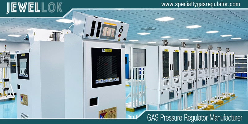
A centralized laboratory gas supply system integrates gas sources, manifolds, regulators, pipelines, valves, monitoring devices, and point-of-use equipment into a controlled distribution network. When properly designed, it can provide stable gas delivery, improve laboratory organization, simplify gas management, and support safer laboratory operations.
The most important design factors include gas type, purity, pressure, flow rate, material compatibility, pipeline sizing, redundancy, monitoring, and safety controls. High-purity applications require additional attention to internal surface condition, cleaning, welding, contamination control, and leak testing.
For laboratories handling multiple gases or operating large numbers of instruments, a professionally engineered centralized gas distribution system can provide a scalable foundation for long-term laboratory operation. The final design, installation, testing, and commissioning should always follow applicable local regulations, recognized engineering standards, gas supplier requirements, and the specific requirements of the laboratory process.
For more about centralized laboratory gas supply system: design, components and installation guide, you can pay a visit to Jewellok at https://www.specialtygasregulator.com/product-category/specialty-gas-cabinet/ for more info.
-
Ultra High Purity Gas Delivery Systems And Liquid Chemical Delivery Systems JW-300-LDS
-
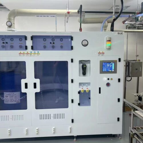
Chemical Delivery Modules for Automated Blending and Precise Dilution in Modern Wafer Cleaning Applications
-
VMB Valve Manifold Panels And Boxes High Purity Configurable Systems JW-200-VMB & JW-100-VMB
-
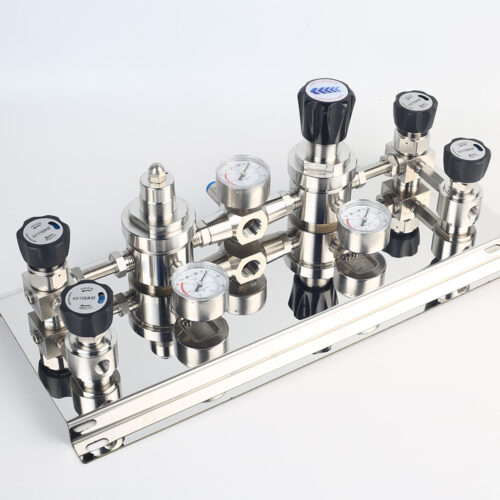
Stainless Steel Single Stage Semiconductor Grade Pressure Control Module Pressure Control Panels JSP-6A Series
-
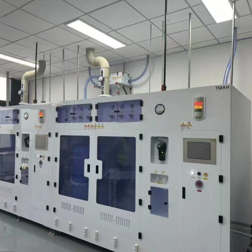
Custom Bulk Chemical Delivery System and Automatic Chemical Dispense Unit (CDU) for Solar Cell and EV Battery Production
-
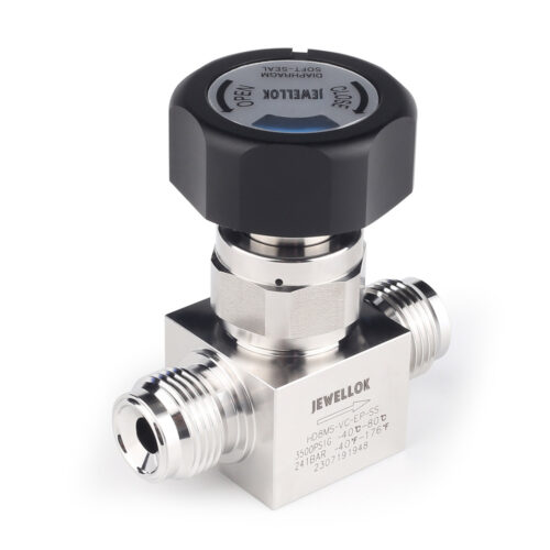
Stainless Steel Ultra High Purity (UHP) High Pressure Manual Diaphragm Valve
-
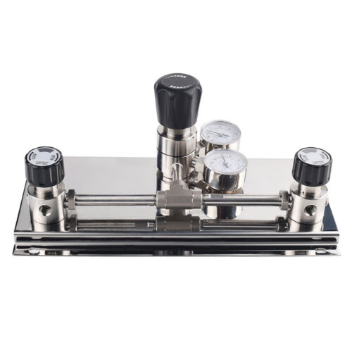
Semi Automatic Oxygen Nitrogen Helium Argon Gas Changeover Manifold Manual Gas Changeover Manifold Panel For Gas Cylinders
-
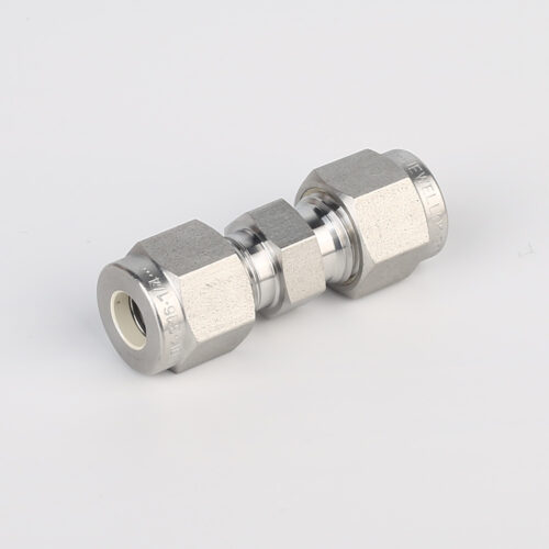
762L Stainless Steel High Purity Union High-Purity Gas System Fittings