
Regulator Manufacturer Tel: +86 13380377051
Regulator Manufacturer Tel: +86 13380377051

How do You Perform Pressure and Leak Testing on a Laboratory Gas Distribution System?
Ensuring the integrity and safety of a laboratory gas distribution system is paramount. Laboratories routinely handle a wide array of gases—ranging from inert carriers like helium and nitrogen to flammable hydrogen, toxic carbon monoxide, and corrosive or reactive compounds. A compromised pipeline or a minute joint leak can result in catastrophic fires, asphyxiation, toxic exposure, or the contamination of high-purity analytical samples.
Consequently, rigorous pressure and leak testing must be performed prior to commissioning any new installation, following major modifications, or during routine periodic recertification. This technical guide outlines the engineering principles, preparation steps, step-by-step testing procedures, advanced leak detection methodologies, and compliance documentation required to safely pressure test a laboratory gas piping network.

1. Regulatory Frameworks and Engineering Standards
Before turning a single valve, engineers and technicians must align their procedures with recognized international and national standards. Key governing bodies include:
-
ASME B31.3: Process Piping Code, which outlines design, material selection, fabrication, inspection, and testing criteria.
-
NFPA 55: Standard for the Storage, Use, and Handling of Compressed Gases and Flammable Fluids in Portable and Stationary Containers, Cylinders, and Tanks.
-
CGA (Compressed Gas Association): Guidelines regarding high-purity piping design, cleaning for oxygen service (CGA G-4.1), and safe handling.
-
OSHA: Occupational Safety and Health Administration regulations regarding compressed gas safety in workplaces.
Typically, the testing protocol mandates a pneumatic test (using gas rather than liquid) because laboratory gas lines are rarely designed to hold the deadweight of water, and residual moisture can severely contaminate ultra-high purity (UHP) gas streams.
2. Pre-Testing Preparations and Safety Protocols
Pneumatic pressure testing introduces significant potential energy hazards because compressed gases expand rapidly upon catastrophic failure. Safety is the top priority.
2.1 Selecting the Test Medium
-
Always use an inert gas such as dry, oil-free nitrogen or high-purity argon.
-
NEVER use oxygen or air-hydrocarbon mixtures for pressure testing, as trace oils combined with pressurized oxygen can cause a spontaneous ignition or explosion.
2.2 System Isolation and Protection
-
Isolate downstream equipment: Sensitive instrumentation, mass spectrometers, gas chromatographs, and analytical equipment must be completely disconnected or isolated using block valves. Point-of-use regulators, relief valves, and flow meters should be removed or protected if the test pressure exceeds their maximum rating.
-
Establish a safety perimeter: Restrict access to the testing area, post clear warning signs indicating “CAUTION: PNEUMATIC PRESSURE TESTING IN PROGRESS,” and ensure only authorized, trained personnel are present.
-
Check mechanical integrity: Verify that all tube fittings (such as Swagelok or VCR face-seal fittings) are fully tightened to manufacturer specifications. Never rely on hand-tightened components.
3. Step-by-Step Pressure Testing Procedure
A standard pneumatic pressure test follows a controlled, stepped pressurization sequence to mitigate risks and identify major flaws before reaching peak test pressures.
Step 1: Define Test Boundaries and Attach Gauges
-
Clearly mark the test boundaries using closed laboratory gas distribution system valves or blank test caps.
-
Install calibrated pressure-measuring devices (digital manometers or analog pressure gauges conforming to ASME standards) at both the high-pressure supply end and the furthest downstream point (the dead-end or remote manifold) to ensure uniform pressure distribution. The gauge range should be selected so that the test pressure falls within the middle third of the scale (typically 1.5 to 2 times the maximum working pressure).
Step 2: Initial Low-Pressure Proofing
-
Gradually introduce the inert test gas into the system until reaching an initial proofing pressure of approximately 25 psi or 25% of the final test pressure (whichever is lower).
-
Hold this pressure for 10 minutes. Conduct a preliminary sweep using a portable electronic sniffer or bubble solution to catch gross assembly errors or loose fittings before escalating stored energy.
Step 3: Stepped Pressurization to Design Factor
-
Per standard industrial guidelines (such as ASME B31.3), the pneumatic test pressure should be 1.5 times the maximum allowable working pressure (MAWP), but it must never exceed the pressure rating of the weakest component in the line (e.g., valves, flexible hoses, or low-pressure regulators).
-
Increase the pressure in controlled increments (e.g., 25% steps every 5 minutes), allowing the system and ambient temperature to stabilize at each tier.
Step 4: The Holding Period and Thermal Stabilization
-
Once target test pressure is achieved, isolate the gas supply source by closing the supply valve.
-
Allow a minimum 15 to 30-minute thermal stabilization period (or up to 24 hours for extensive, complex distribution networks). Gas temperature changes directly affect pressure (Ideal Gas Law: PV=nRTPV = nRT). Monitoring ambient temperature alongside pressure ensures that minor pressure fluctuations are properly interpreted rather than falsely flagged as leaks.
4. Advanced Leak Detection Methodologies
Once the pressure has stabilized, technicians must perform a comprehensive leak check across every weld, joint, threaded connection, valve stem packing, and mechanical fitting.
Note on Bubble Testing: Ensure that the leak detection fluid used is compatible with the piping material (e.g., chloride-free for austenitic stainless steel to prevent stress corrosion cracking) and thoroughly cleaned afterward.
5. Post-Testing and Commissioning Phase
Successfully passing the pressure and leak test transitions the system into the final sign-off and purging stages.
-
Controlled Depressurization: Slowly open a downstream vent valve to bleed off the test pressure in a safe, well-ventilated area. Avoid rapid venting, which can shock components or cause Joule-Thomson cooling effects.
-
Purging and Dehydration: If testing was performed with nitrogen, purge the network extensively with the intended working gas (or ultra-pure grade) through multiple vacuum-purge or pressure-purge cycles to eliminate residual moisture, oxygen, and particulate matter.
-
Documentation and Certification: Record all test parameters—including ambient temperature, initial pressure, final pressure, test duration, gauge calibration serial numbers, and technician signatures. Compliance documentation must be archived in the facility’s safety management system.
-
Reconnection: Re-install point-of-use regulators, analyzers, and safety relief devices, followed by a final low-pressure functional check with the actual working gas.

Conclusion
Performing pressure and leak testing on a laboratory gas distribution system is a critical engineering safeguard that protects personnel, facilities, and expensive analytical equipment. By adhering to strict standards like ASME and NFPA, executing controlled stepped pressurization, and employing appropriate leak detection modalities (from bubble tests to helium mass spectrometry), laboratory managers can guarantee a safe, reliable, and leak-free gas delivery infrastructure.
For more about how do you perform pressure and leak testing on a laboratory gas distribution system, you can pay a visit to Jewellok at https://www.specialtygasregulator.com/product-category/specialty-gas-cabinet/ for more info.
-
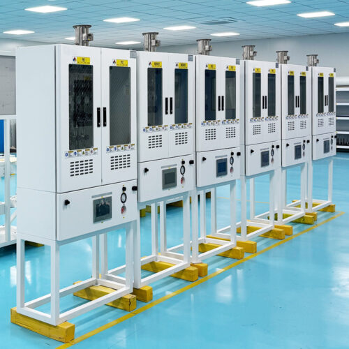
Precision Stainless Steel Valve Manifold Panel for Inert Gas Distribution in Cleanroom Manufacturing Environments
-
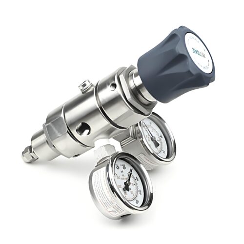
DPR1 Ultra High Purity Two Stage Dual Stage Pressure Reducing Regulator Semiconductor Grade Regulators
-
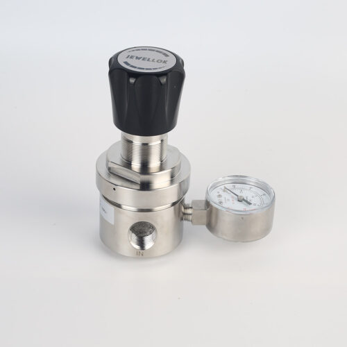
Line And Panel Mounting Adjustable Low Pressure Propane And Nitrogen Pressure Regulator JSR-3L & JSR-3LP Series
-
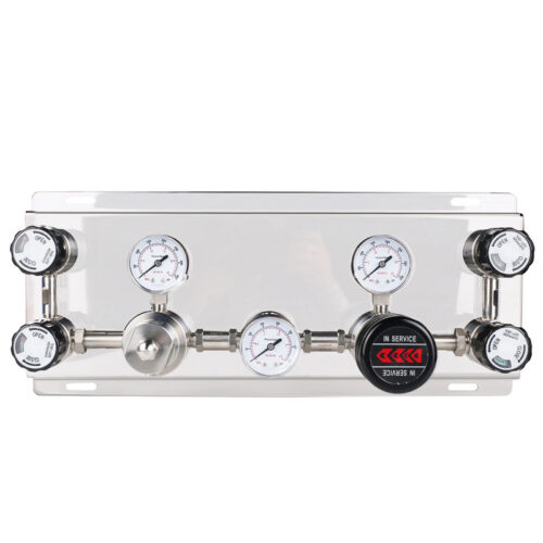
Semi Automatic And Automatic Switching Speicialty Gas Changeover Manifold Panel With Semiconductor Valve Manifold Box Gas Pressure Regulators
-
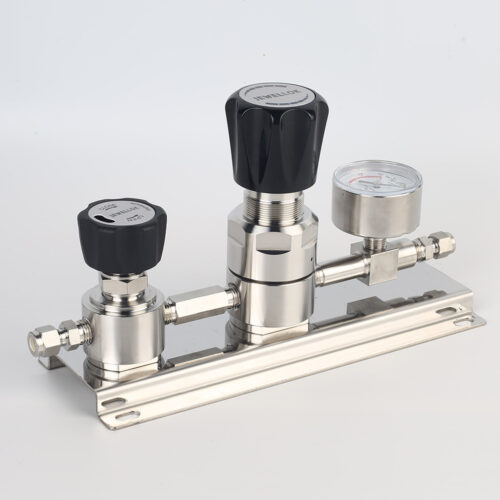
High Purity High Flow Pressure Control Regulators & Valves Gas Stick Assemblies JSR-2TG Series
-
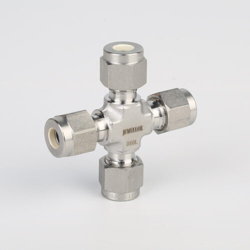
7102L Stainless Steel 316L SS Union Cross Ultra High Purity Long Arm Union Elbow Tee Cross Butt Weld Fittings
-
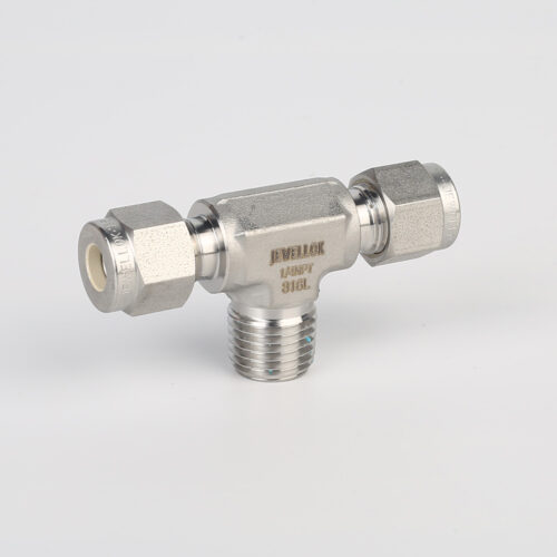
772L Male Branch Tee | Stainless Steel High-Purity Tube Fitting Male Branch Tee
-
Corrosion Resistant 316L Stainless Steel Exhaust Gas Scrubber System for Harsh Chemical Process Environments