Regulator Manufacturer Tel: +86 13380377051
Regulator Manufacturer Tel: +86 13380377051
")
How Does an LPG Gas Manifold System Work?
The Central Nervous System of Bulk LPG Supply
In residential, commercial, and industrial settings where multiple gas appliances operate simultaneously—from kitchen ranges and water heaters to industrial furnaces—a safe, efficient, and centralized gas distribution system is essential. This is where the Liquefied Petroleum Gas (LPG) manifold system comes into play. Often described as the “central nervous system” of a bulk LPG installation, a manifold system replaces multiple individual gas cylinders with a unified setup that enhances safety, ensures consistent supply, and simplifies operations. This technical article will delve into the components, working principles, design considerations, and safety mechanisms of a typical LPG manifold system, providing a clear understanding of its engineering and operation.
- What is an LPG Manifold System?
An LPG manifold system is a gas distribution arrangement that connects two or more LPG cylinders (or larger storage vessels) to a common header or manifold. This header then supplies gas via a single pipeline to multiple appliances. The primary purposes are:
- Increased Gas Supply Capacity: By connecting multiple cylinders, the system extends the available gas supply duration before replacement is needed.
- Automatic Changeover: It enables automatic switching from an empty set of cylinders to a full set without interrupting the gas supply.
- Pressure Regulation and Stabilization: It ensures a steady, regulated gas pressure to all connected appliances.
- Enhanced Safety: Centralized shut-off valves, leak detection points, and pressure relief mechanisms improve overall safety.
- Operational Convenience: Reduces the frequency of cylinder changes and allows for remote monitoring.
These systems are commonly used in restaurants, hospitals, laboratories, industrial plants, and large residential complexes where gas demand exceeds the capacity of a single cylinder.
- Key Components of an LPG Gas Manifold System
Understanding the system requires familiarity with its core components, each playing a specific role in the safe delivery of gas.
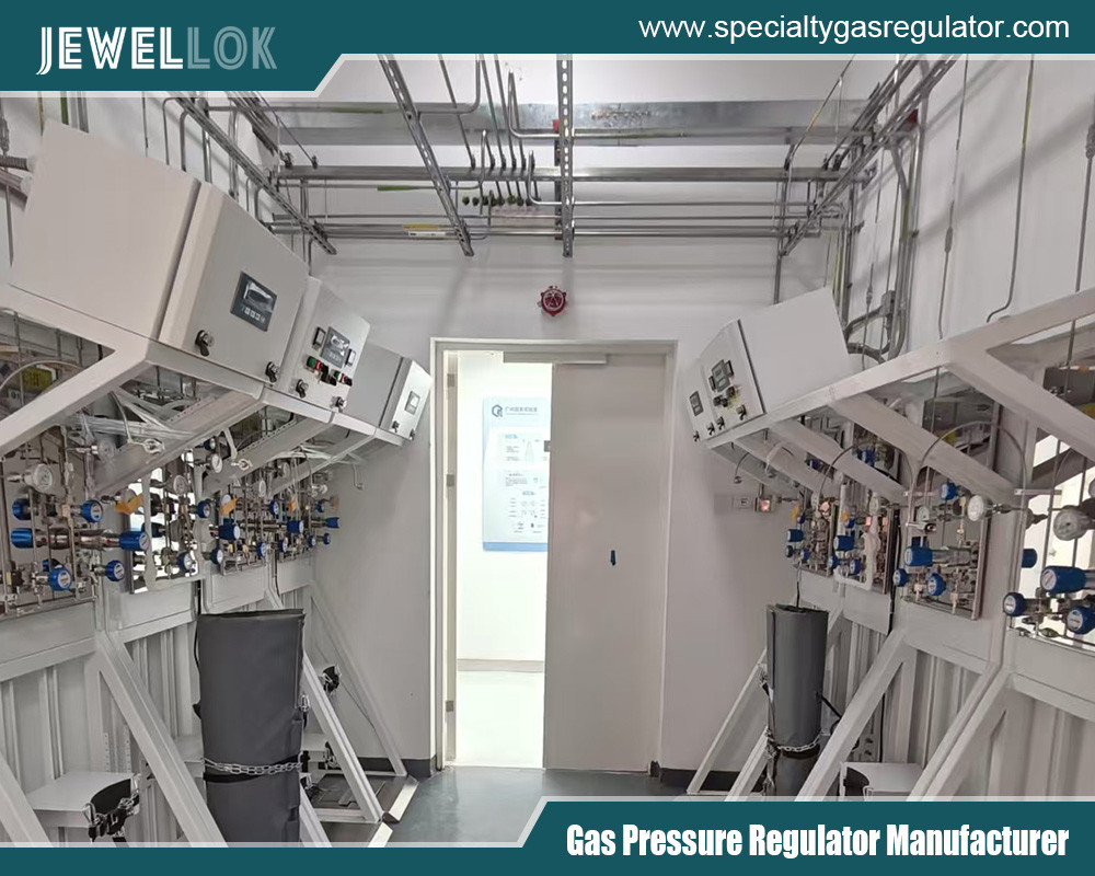
2.1 Cylinder Banks
Cylinders are grouped into two separate banks: the primary (active) bank and the secondary (reserve) bank. Typically, each bank consists of multiple cylinders connected in parallel. The number of cylinders per bank depends on the gas consumption rate and desired supply duration. Cylinders are securely held in a frame or cage for stability.
2.2 Manifold (Header Pipe)
The manifold is a robust pipe (usually copper or steel) that runs between the cylinder banks. It collects gas from all cylinders in a bank and consolidates it into a single outlet. It must be sized correctly to handle the maximum possible flow rate without excessive pressure drop.
2.3 Automatic Changeover Valve (ACV)
This is the brain of the system. The ACV continuously monitors the pressure in the primary bank. When the primary bank is nearly empty (pressure drops to a pre-set level, typically around 0.7 bar or 10 psi), the valve automatically switches the gas supply to draw from the secondary bank. Simultaneously, it often activates a visual or audible indicator (e.g., a red flag or buzzer) to alert users that the primary bank needs replacement.
2.4 High-Pressure Flexible Hoses
These reinforced hoses connect the outlet valves of individual cylinders to the manifold. They are designed to withstand high LPG pressure (up to ~17 bar or 250 psi) and are fitted with proper safety shut-off valves.
2.5 Regulators (Two-Stage Pressure Reduction)
LPG in cylinders is stored as a liquid under high pressure (approx. 5–10 bar at ambient temperature). The manifold system typically employs a two-stage regulation process:
- First-Stage Regulator (Bank Regulator): Often attached directly to the manifold or changeover valve, this reduces the high cylinder pressure to an intermediate pressure (e.g., 0.7–1.4 bar).
- Second-Stage Regulator (Appliance Regulator): Located nearer to the appliances, this further reduces the intermediate pressure to the appliance working pressure (typically 28–37 mbar for LPG). In some designs, a single regulator may suffice if placed correctly.
2.6 Shut-Off Valves
- Manual Isolation Valves: Installed at various points (cylinder outlets, manifold inlets/outlets) to allow manual isolation for maintenance or emergencies.
- Excess Flow Valves: Often integrated, these automatically shut off the gas flow if a sudden, large flow is detected (indicating a possible line rupture).
2.7 Pressure Relief Valve (PRV)
Fitted to the manifold, the PRV protects the system from over-pressurization due to thermal expansion or regulator failure. It vents gas safely to the atmosphere if pressure exceeds a set limit.
2.8 Pressure Gauges
Gauges may be installed to monitor pressure at key points: cylinder bank pressure, manifold pressure, and regulated pressure. They aid in diagnostics and operational checks.
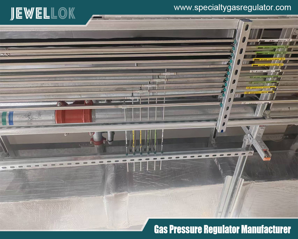
2.9 Piping Network
From the manifold outlet, gas travels through a correctly sized distribution pipework (often copper or CSST) to the various appliance locations. The pipe sizing follows gas load calculations and local codes to ensure adequate flow at all points.
- The Working Principle: Step-by-Step Operation
The operation of an LPG manifold system can be broken down into a continuous cycle.
Step 1: Gas Withdrawal from Primary Bank
Under normal operation, the automatic changeover valve is set to draw gas from the primary bank. LPG (a mixture of propane and butane) exists as liquid in the bottom of the cylinders. As gas is withdrawn from the top, the liquid evaporates to replace it, maintaining pressure until the liquid is nearly exhausted. The high-pressure gas (cylinder pressure) flows through individual cylinder valves, through flexible hoses, and into the common manifold.
Step 2: Pressure Regulation
The combined high-pressure gas from the active bank enters the first-stage regulator via the changeover valve. Here, pressure is reduced significantly to an intermediate level suitable for distribution through longer pipelines without excessive pressure drop.
Step 3: Distribution to Appliances
The regulated gas flows through the main distribution pipe. At each appliance or group branch, a second-stage regulator (if used) fine-tunes the pressure to the specific requirements of the appliance burner. The gas then passes through the appliance’s own gas valve for use.
Step 4: Automatic Changeover Process
As the primary bank cylinders empty, the pressure in the manifold downstream of the cylinders begins to drop. The automatic changeover valve senses this pressure drop. Once it reaches the pre-set “changeover pressure,” the valve’s internal mechanism shifts:
- It closes the inlet port from the primary bank.
- It opens the inlet port from the secondary (full) bank.
- Gas supply is now seamlessly drawn from the secondary bank without any interruption to the appliances.
- A visual indicator (like a pop-up red flag) shows “RESERVE IN USE,” signaling that the primary bank needs servicing.
Step 5: Cylinder Replacement and Reset
An operator replaces the empty cylinders in the primary bank. Once the new cylinders are connected and their valves opened, the changeover valve can be manually reset. This resets the indicator and prepares the system to draw from the freshly filled primary bank again, while the secondary bank becomes the new reserve. Some advanced systems may have auto-reset features.
Step 6: Continuous Cycle
This process repeats indefinitely, ensuring an uninterrupted gas supply as long as one bank always contains fuel.
- Design Considerations and Sizing Calculations
Proper system design is critical for safety and performance. Key factors include:
4.1 Determining Gas Demand
The total connected load of all appliances (measured in kW or BTU/hr) is calculated. From this, the maximum probable gas flow rate (in kg/hr or lb/hr) is derived, accounting for diversity factors (not all appliances run simultaneously).
4.2 Sizing the Manifold and Piping
Using the flow rate and allowable pressure drop (as per standards like NFPA 54 or EN 15266), engineers select appropriate pipe diameters for the manifold and distribution lines to ensure adequate pressure at the farthest appliance.
4.3 Cylinder Bank Sizing
The number of cylinders per bank is determined by:
- The gas consumption rate.
- Desired hours of operation before changeover.
- Physical space and safety clearance requirements.
A common rule is to size each bank to supply gas for a minimum period (e.g., 24 hours under peak demand).
4.4 Ventilation and Location
The cylinder banks and manifold must be located in a well-ventilated, secure area, preferably outdoors or in a dedicated ventilated enclosure, to prevent accumulation of leaked gas. Clearances from ignition sources, building openings, and property lines must comply with local regulations.
4.5 Materials Compatibility
All components (hoses, seals, valves) must be compatible with LPG. For instance, certain elastomers degrade with LPG, so only approved materials should be used.
- Safety Systems and Integral Protections
Safety is paramount in any gas system. Manifold systems incorporate multiple layers of protection:
5.1 Leak Prevention
- Leak-Tight Connections: Use of proper fittings (e.g., flare fittings) and thread sealants compatible with LPG.
- Regular Soap Solution Testing: Mandatory during installation and maintenance.
5.2 Over-Pressure Protection
- Pressure Relief Valve on Manifold: Set to a pressure above normal operating range but below the weakest component’s rating.
- Regulator Failure Protection: Some regulators have built-in relief or shut-off if downstream pressure rises abnormally.
5.3 Under-Pressure and Flow Protection
- Automatic Changeover Valve: Prevents complete depletion of all cylinders, which could allow air to enter the system.
- Excess Flow Valves: Installed at the cylinder or manifold inlet, these close if flow exceeds a safe limit (e.g., from a ruptured hose).
5.4 Fire Safety
- Thermally Activated Shut-Off Valves (Fusible Links): These melt at high temperature (e.g., 100°C), shutting off the gas supply in case of fire.
- Fire-Rated Barriers: May be required between cylinder banks and buildings.
5.5 Operational Safety
- Clear Labeling: Banks marked “Active” and “Reserve.”
- Emergency Shut-Off Valve: A clearly accessible master valve to isolate the entire system quickly.
- Installation, Commissioning, and Maintenance
6.1 Installation
Must be performed by certified gas fitters following national and local codes (e.g., Gas Safe Register in the UK, NFPA in the US). Key steps include securing cylinder racks, installing pipelines with proper supports, and ensuring electrical bonding for static dissipation.
6.2 Commissioning
After installation, the system must be:
- Pressure tested (strength and tightness tests) using inert gas.
- Purged of air before introducing LPG.
- Checked for correct changeover operation and regulator output pressure.
6.3 Routine Maintenance
- Daily/Weekly: Visual check of indicators, cylinder condition, and leak detection.
- Monthly: Operational test of changeover valve and verify pressure readings.
- Annually: Comprehensive inspection by a qualified technician, including regulator testing, hose replacement (as per manufacturer’s lifespan, typically 5 years), and valve function checks.
- Advanced Systems and Modern Innovations
Modern LPG gas manifold systems can integrate with building management systems (BMS) for remote monitoring. Features include:
- Telemetry Systems: Wireless sensors send alerts for low gas levels, leaks, or pressure faults to a facility manager’s phone or computer.
- Electronic Changeover: Solenoid-operated valves with electronic pressure sensors for more precise control.
- Bullet Tank Integration: For larger demands, manifolds can connect not only cylinders but also larger LPG storage tanks (bullets), with pumps or vaporizers for increased withdrawal rates.
- Common Applications and Use Cases
- Hospitality: Large restaurant kitchens with multiple burners, ovens, and grills.
- Healthcare: Sterilizers, laundry, and kitchen facilities in hospitals.
- Industrial: Heating processes, metal cutting, forklift refueling stations.
- Residential: Gated communities or apartment blocks with centralized gas distribution.
- Temporary Sites: Construction camps or event catering where temporary but high-volume gas supply is needed.
Conclusion
An LPG manifold system represents a sophisticated solution to the challenge of reliable, high-volume gas distribution. By intelligently automating the switch between cylinder banks and incorporating multiple safety features, it eliminates manual intervention, reduces downtime, and minimizes risks associated with gas handling. Its design principles—redundancy, regulation, and protection—ensure that as long as it is correctly sized, installed, and maintained, it will deliver uninterrupted fuel supply safely and efficiently. For any facility reliant on continuous gas supply, investing in a well-engineered manifold system is not just a matter of convenience but a critical component of operational resilience and safety management.
Understanding how these systems work empowers facility managers, engineers, and safety officers to operate them confidently, respond to issues effectively, and appreciate the engineering that keeps the gas flowing seamlessly behind the scenes.
For more about how does an LPG gas manifold system work, you can pay a visit to Jewellok at https://www.specialtygasregulator.com/product-category/specialty-gas-pressure-regulators/ for more info.
-

Stainless Steel High-Purity High Temperature Metal Seated Ball Valves JBV3 Series
-

Stainless Steel Ultra High Purity Mini Butt Weld Mini Tee Reducer MTRW Series Fittings
-

High Purity Gas Cylinder Semi Automatic Changeover Manifold Regulator Panel 3000psig Stainless Steel Gas Control Panel 1/8 Npt With Gauge
-

Stainless Steel 316L Single Stage Regulator Pressure Control Panels JSP-1E Series For Semiconductor Fluid Control
-

767LP Port Connector Ultra High Purity VCJ Metal Gasket Face Seal Tube Fittings
-

Custom Wet and Dry Exhaust Gas Scrubber System Technology for Effective Acid Gas Neutralization
-

High Purity Chemical Dispense System & Packing System For Semiconductors JW-200L-CDM & JW-1000L-CDM
-

Flow Control Stainless Steel Low Pressure Manual Diaphragm Valve For High Purity And Ultra High Purity Gases